After much more ordering from Mouser and Digikey, we were ready for the arduous task of tackling the install. Due to the nature of the design and the desire to not have any wires showing in the crystal chamber, channels were made under the front shroud to allow the wiring to be concealed underneath. This came at the price of being very tedious to wire and install the electronics. Everything worth having is worth doing right though no matter what right? Now, on to the installation of electronics and the finishing of the Starkillers!
The disassembly of parts:
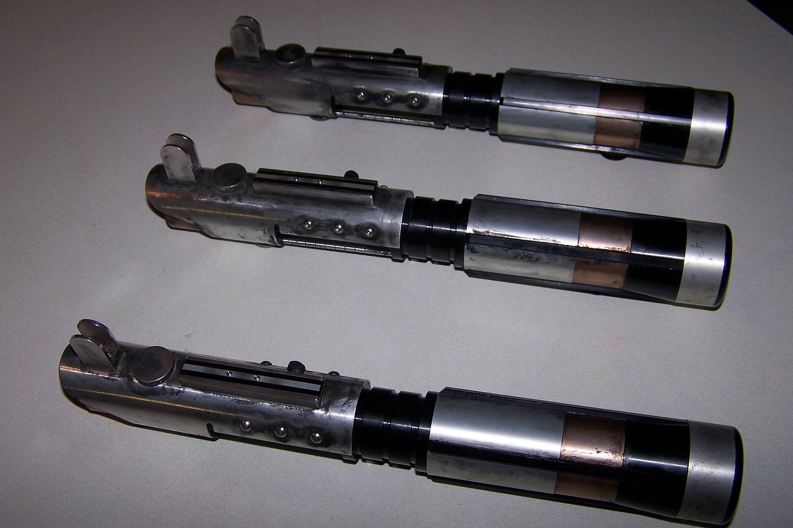
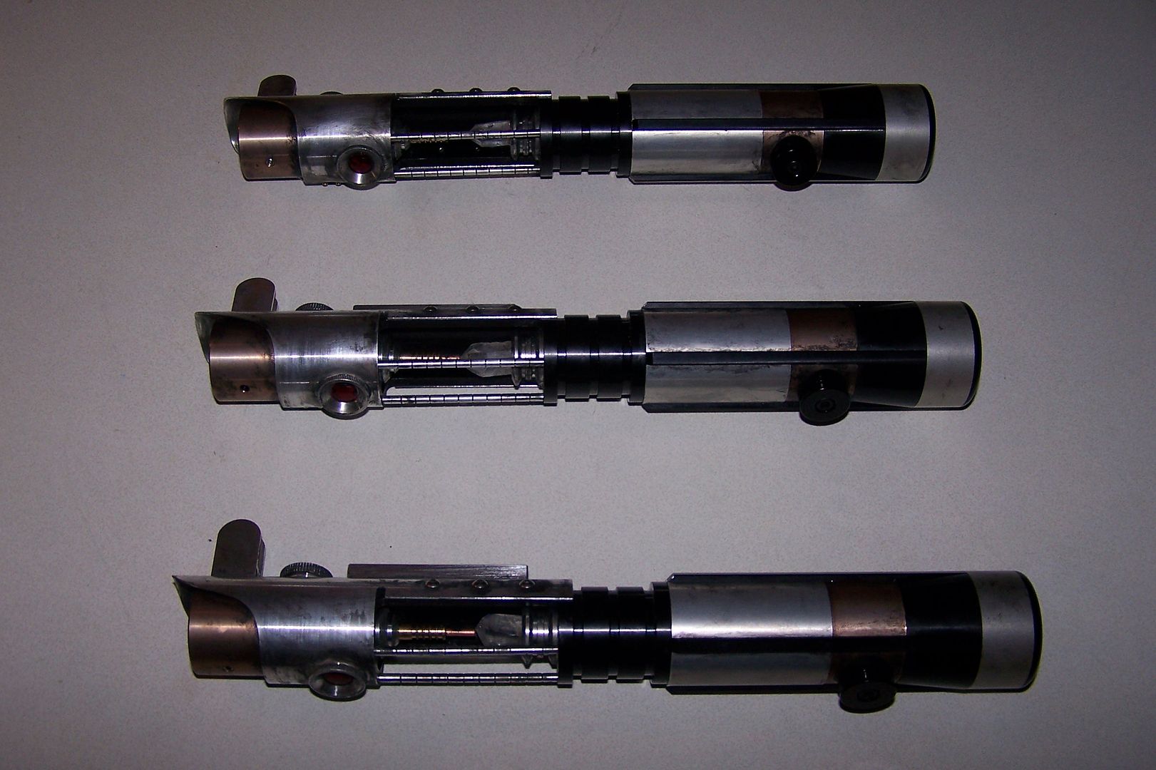
Erik sent us the sabers put together for the most part to ensure that numbered and fitted pieces stayed together, and to make our lives easier (thanks for the chassis Erik, sorry about the arthritis! :011:)
I start with 3 sabers, 3 parts trays and keep the numbered sabers sorted with their parts.
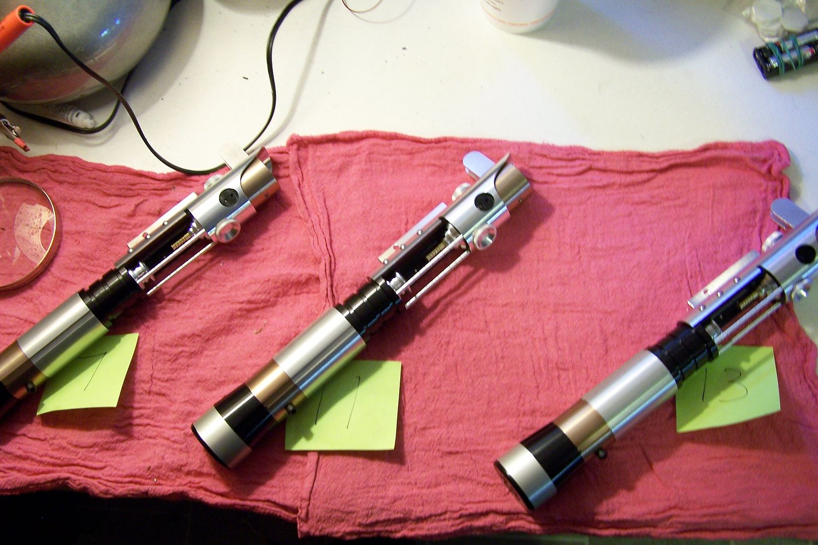
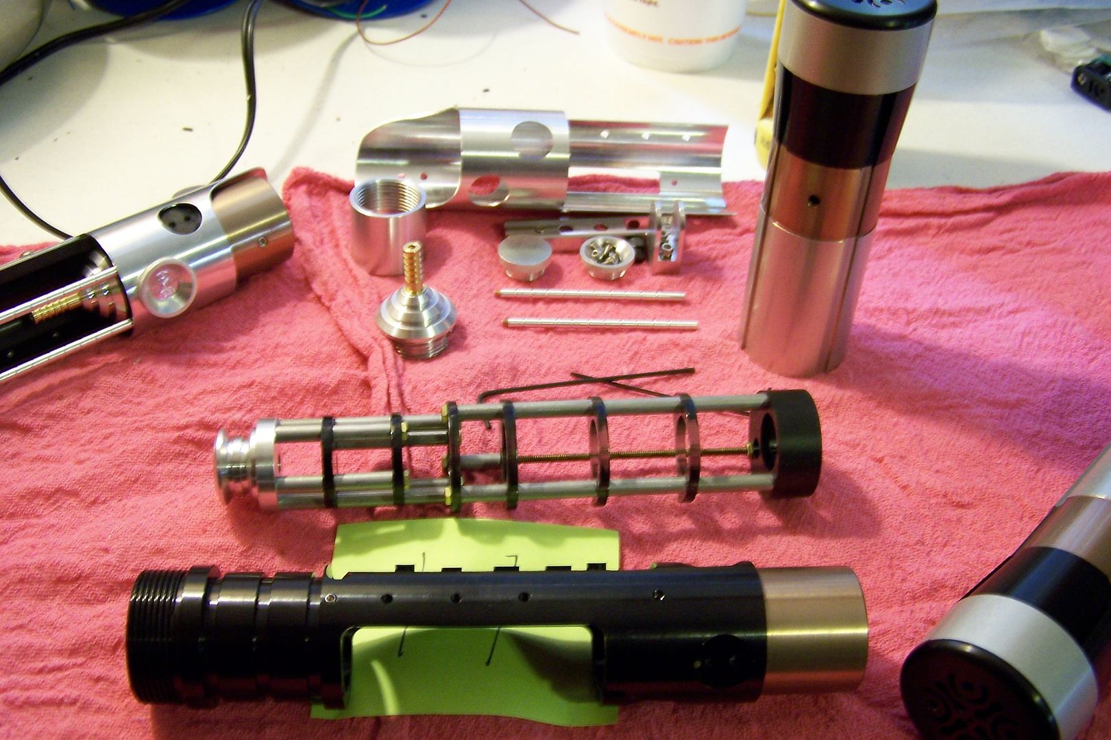
All broken down.
The first thing to get done is the battery packs. 14500 size Li-Ion cells are individually charged then soldered into a stick pack heatshrunk and installed in the channel through the chassis:
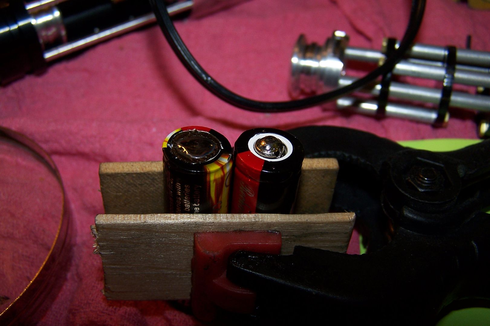
The tabs are scratched to remove the coating to allow for solder adhesion, then they're tinned. I hold my batteries between to cut pieces of paint stirring sticks with a spring clamp.
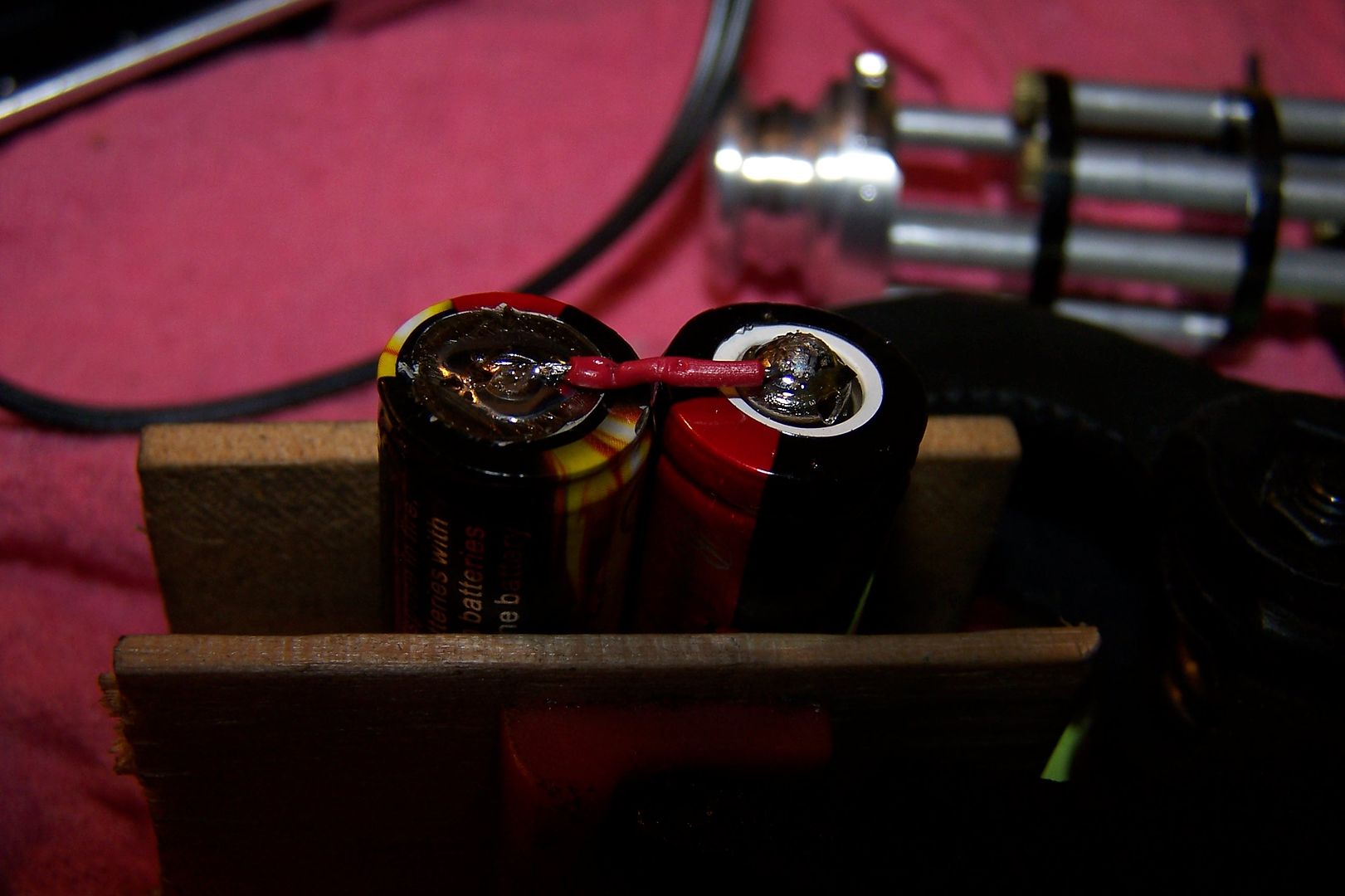
The bridge.
The positive and negative leads.
The ends are sealed with high temp hot glue.
A piece of 3/4" heatshrink is cut to length, fitted over the batteries and then shrunk.
Battery packs are installed in the chassis.
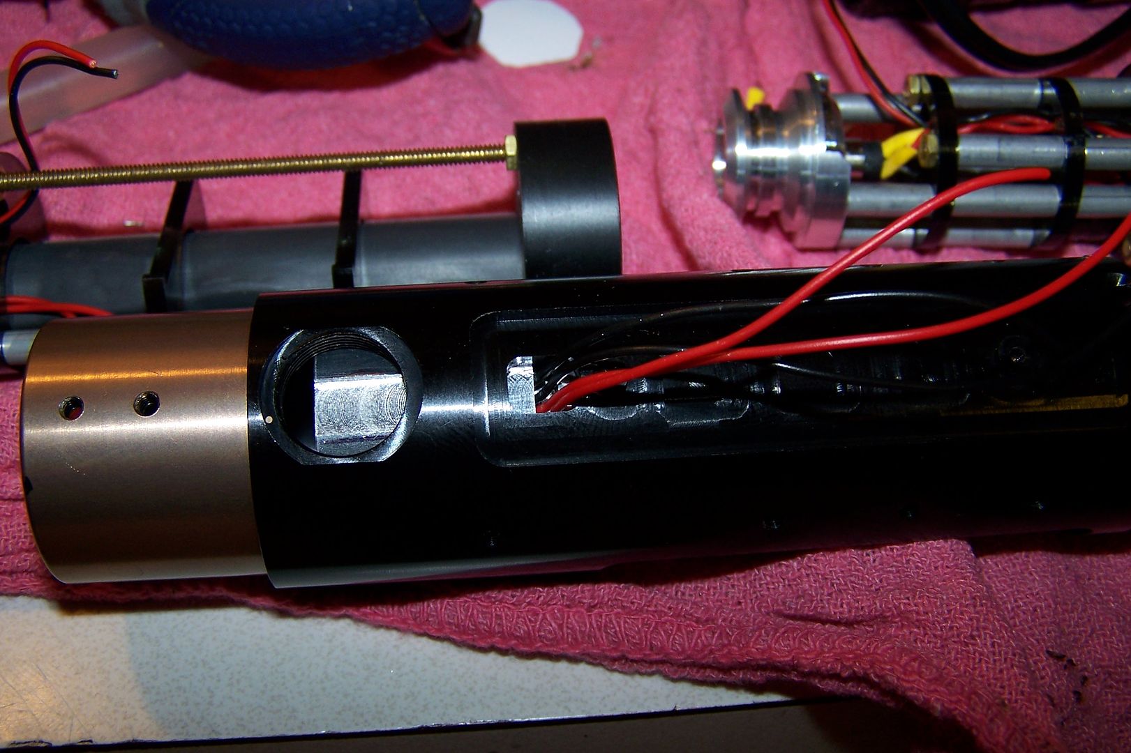
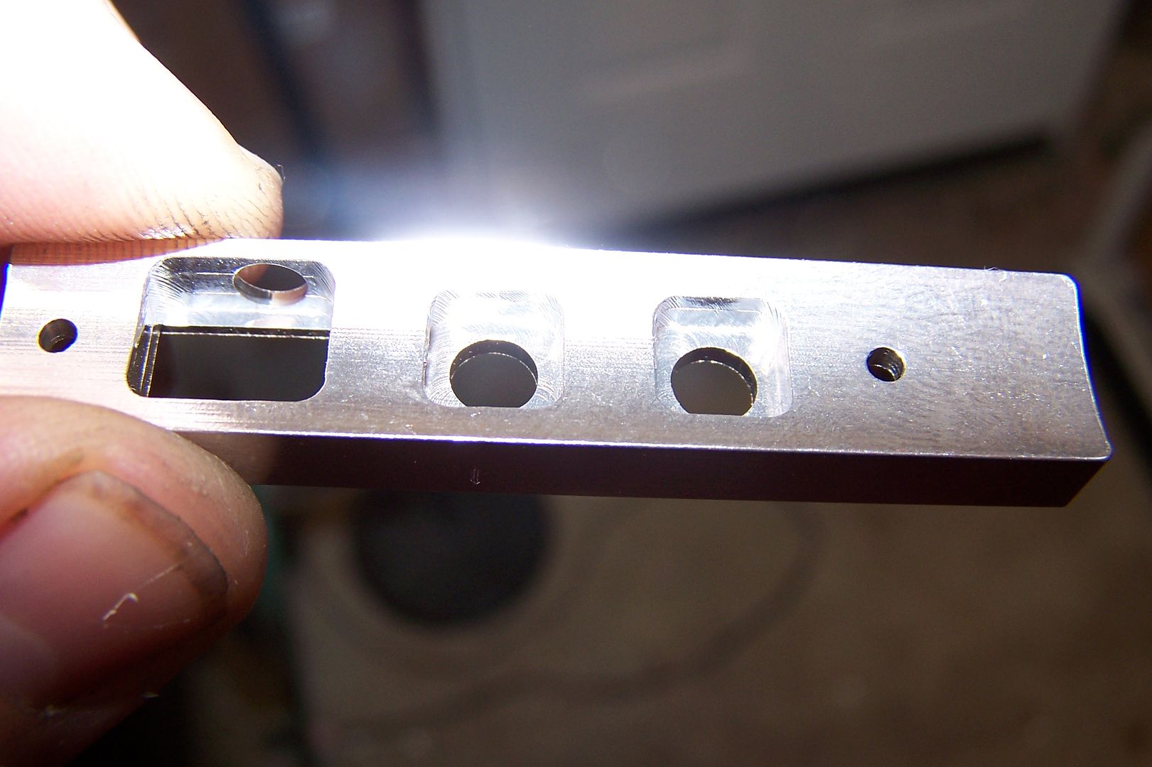
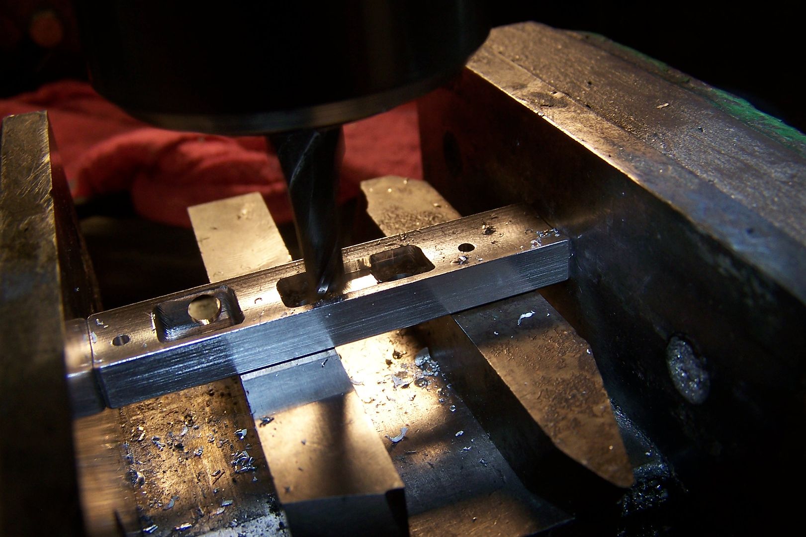
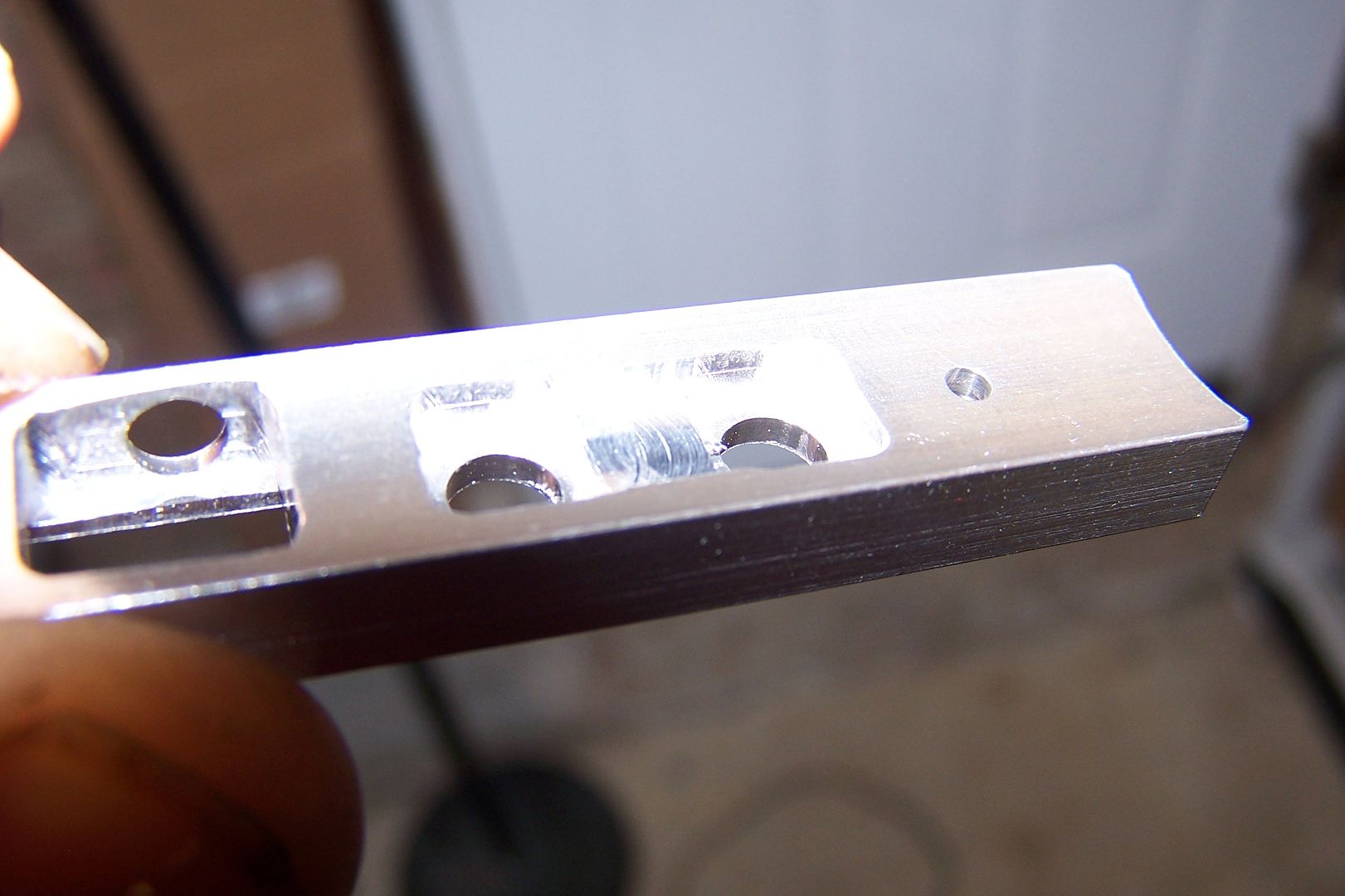
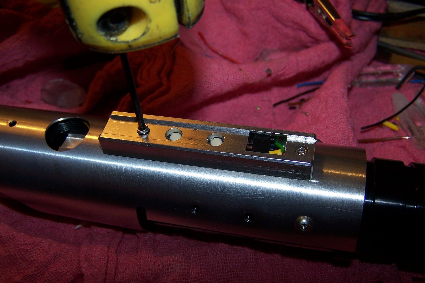
The next thing that has to be done is the optics module. It has to go in and it's wires run before the shroud piece can go on. However, since there really is no guarantee how the optics and wires will line up after threading the heatsink in, I have to mark and mill a slot in the module to allow the wires to pass by.
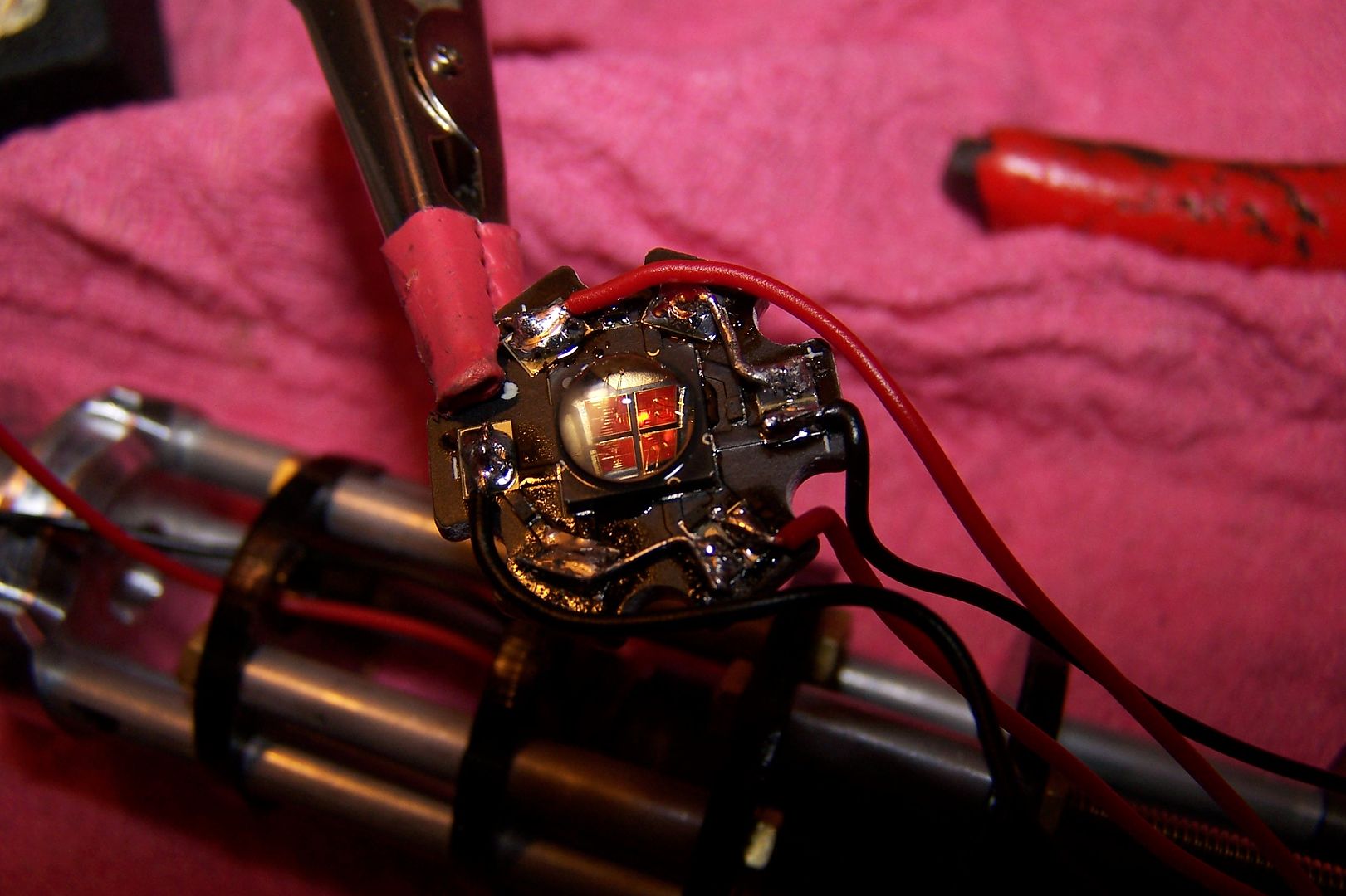
For most of the sabers, we're using the LEDengin 10 Watt red LED. It has 4 individually addressable dice. We're wiring one pair in series for the main blade, and another pair in series for the Flash on Clash effect. I keep a collection of snipped resistor and LED legs around for the purposes of bridging the compact LED pads on these stars. The trick with LEDengins is that they sink heat really well and if you try soldering to them while they're on a heatsink, the solder will never bond and you'll get cold joints. I hold my stars in the jaws of my helping hands and warm the bottom of the star first.
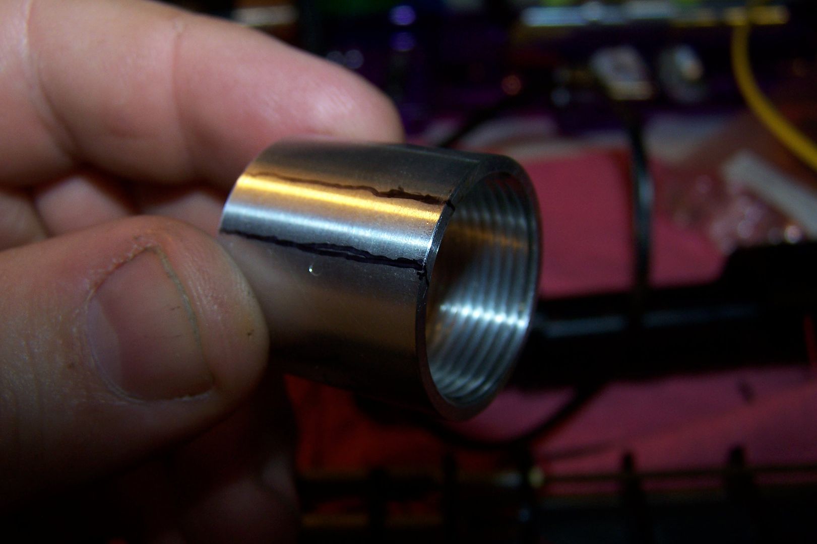
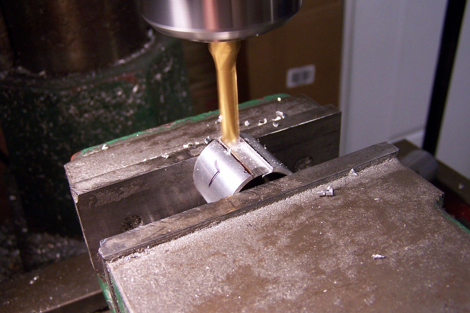
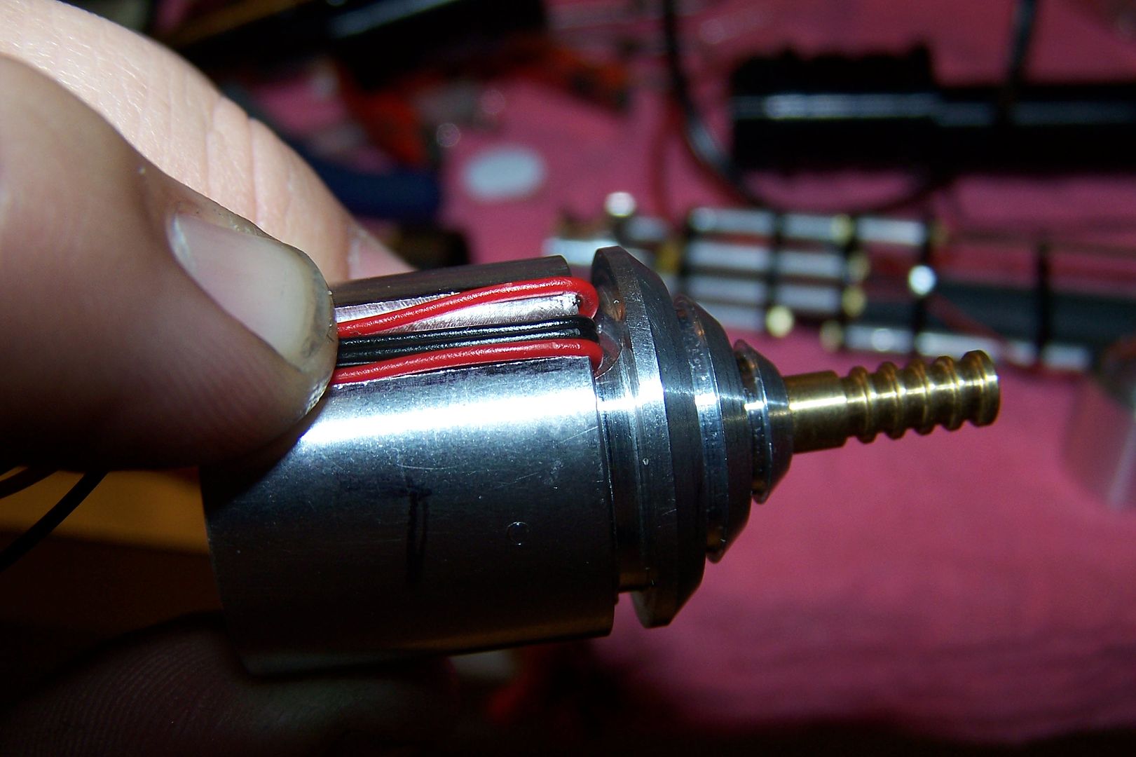
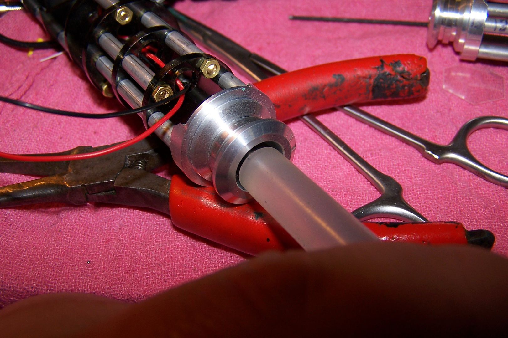
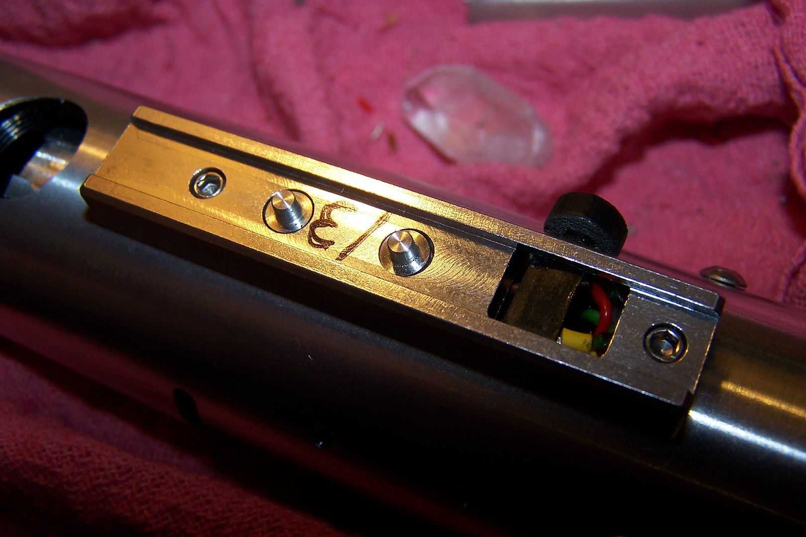
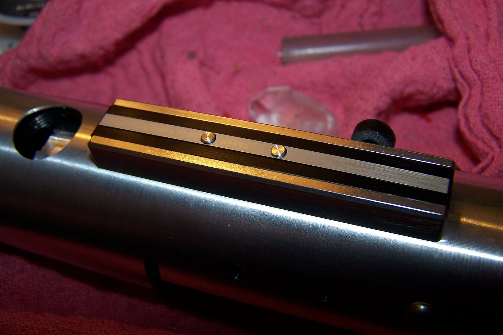
After attaching the star to the heatsink with thermal tape I thread the heatsink into the outer can (optics installed too of course). Once I get it snug, I mark where the wires are on the can so I can mill a channel in the can. This allows me to fold the wires up and over the can to get them through the top port on the hilt.
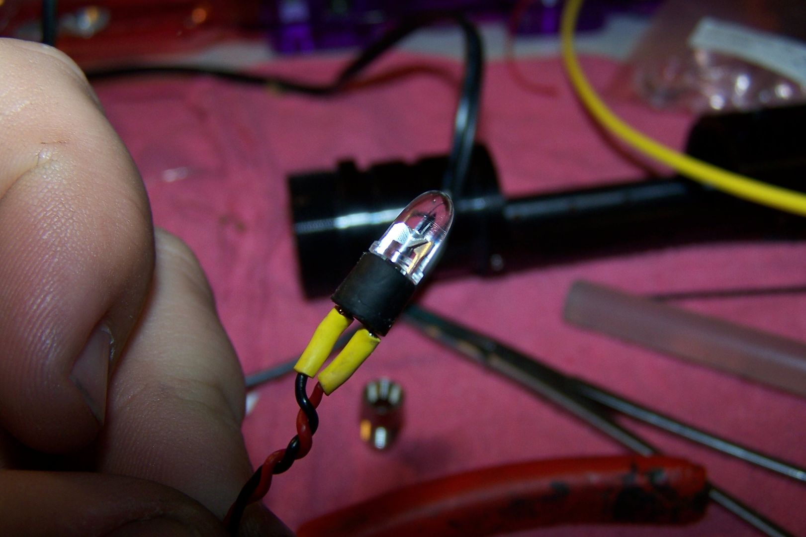
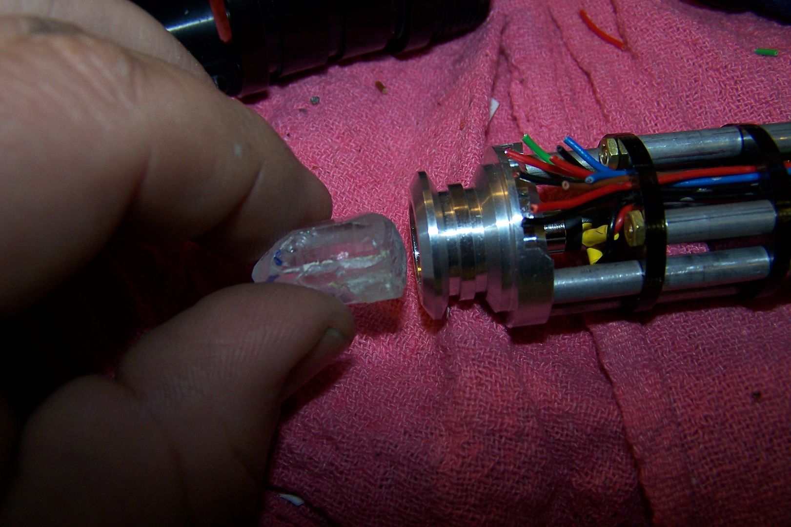
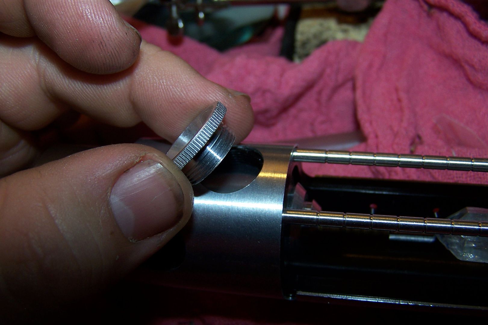
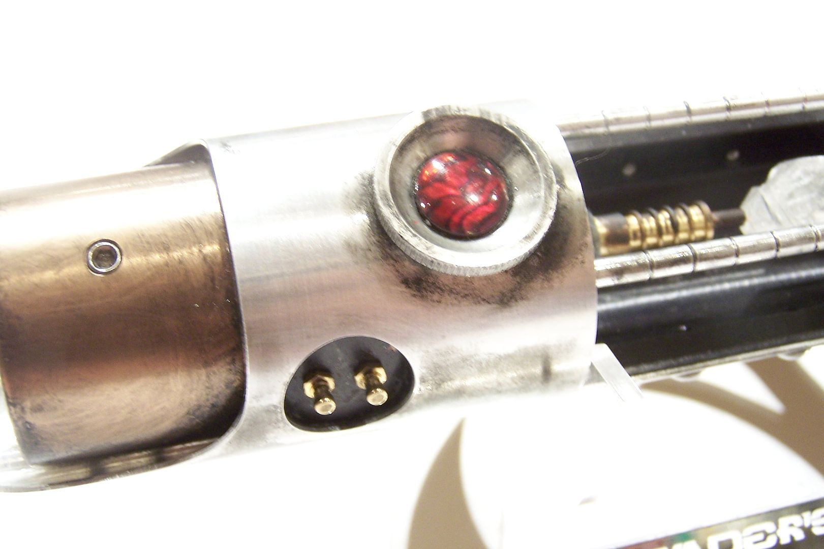
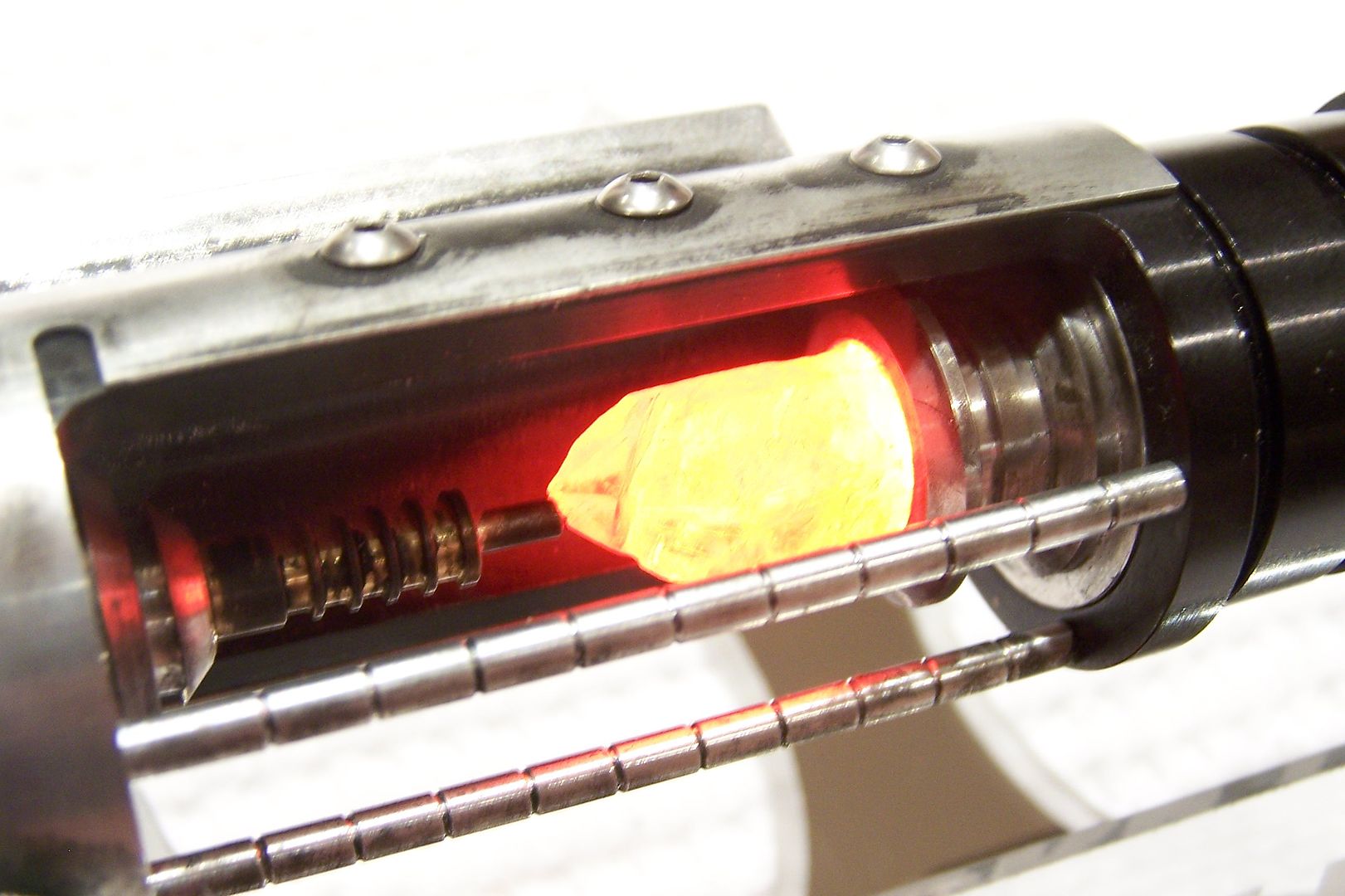
Next up is the chassis, and the crystal chamber. We had to purchase probably 300 crystals to get ones that we liked for each saber. Once I have one picked for a saber, I grind the end flat on the bench grinder (use a breather, you don't want silicosis of the lung) and fit it to the holder. Then I take my 5mm LED bezel that the holder is threaded for and screw it in. I used a glue stick to help thread it in ( I have also used the end of a pencil).
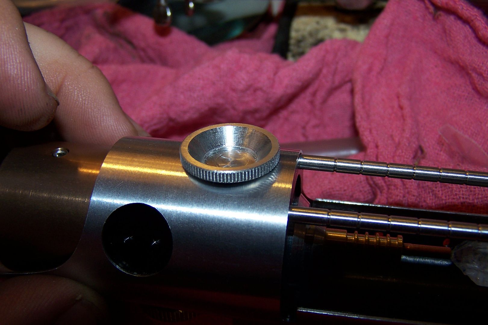
The crystal then needs to be fitted for aesthetics, how it looks when installed and it's orientation. I also need to size, cut and glue in the copper rod spacer that goes between the brass piece on the heatsink and the crystal.
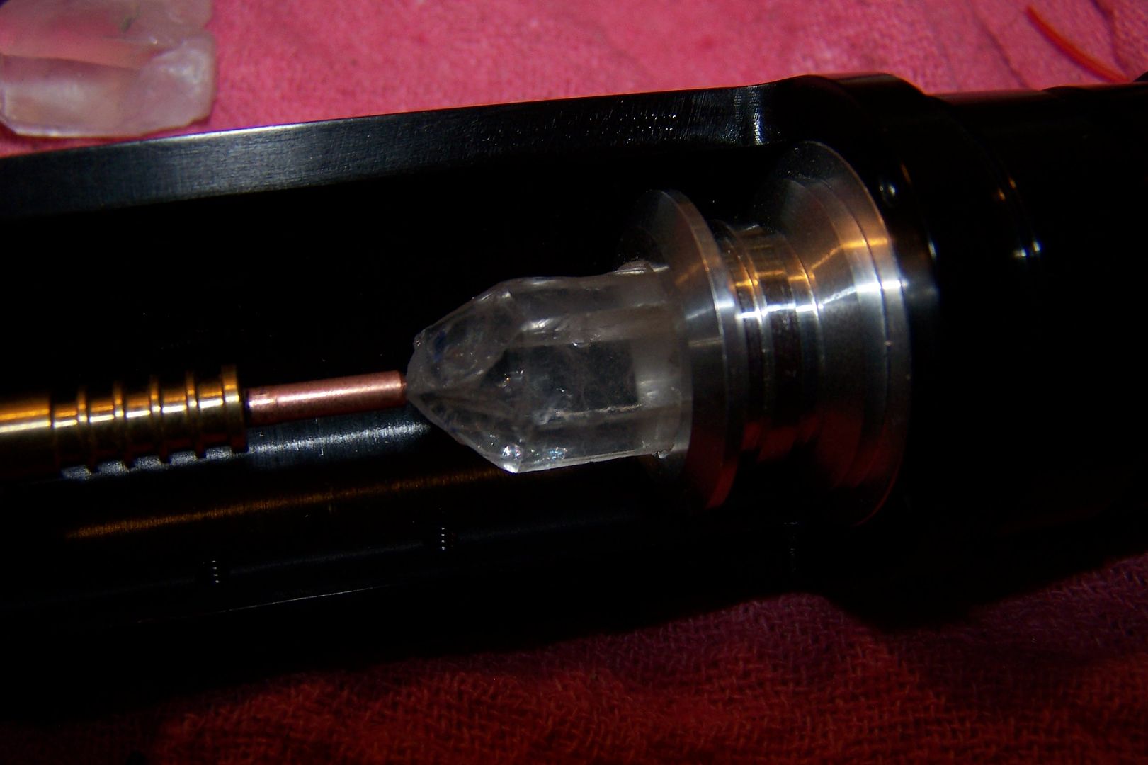
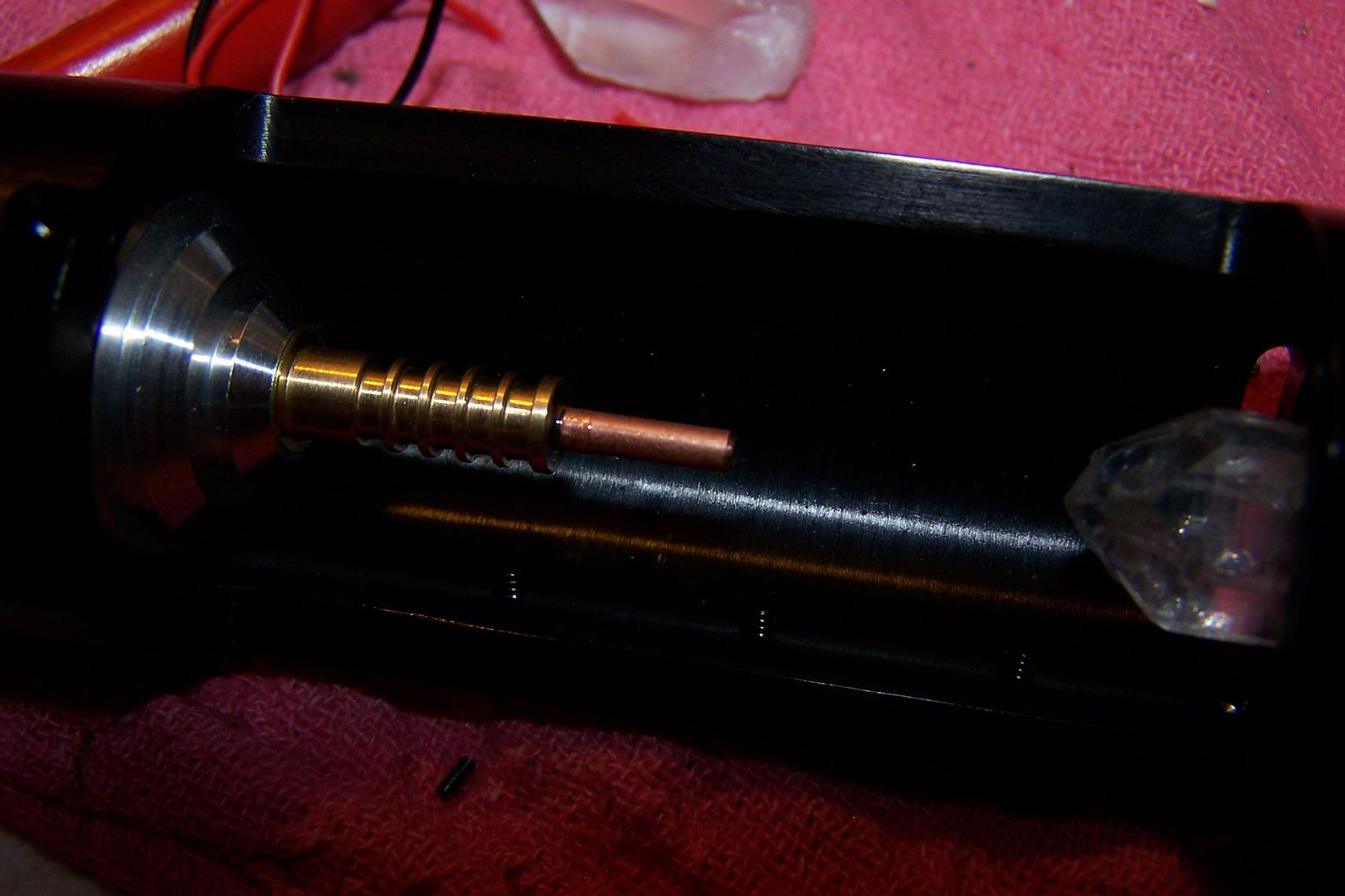
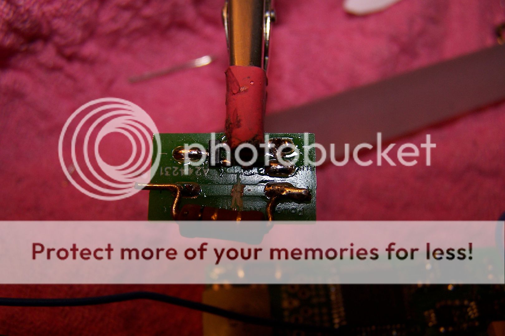
The crystal is then epoxied into it's final resting place and we move on to wiring the soundboard and the power extender board for the Flash on Clash. To save space, I cut the positive trace on the power extender and used the resistor (2 Watt 1 ohm) to bridge the space. CF
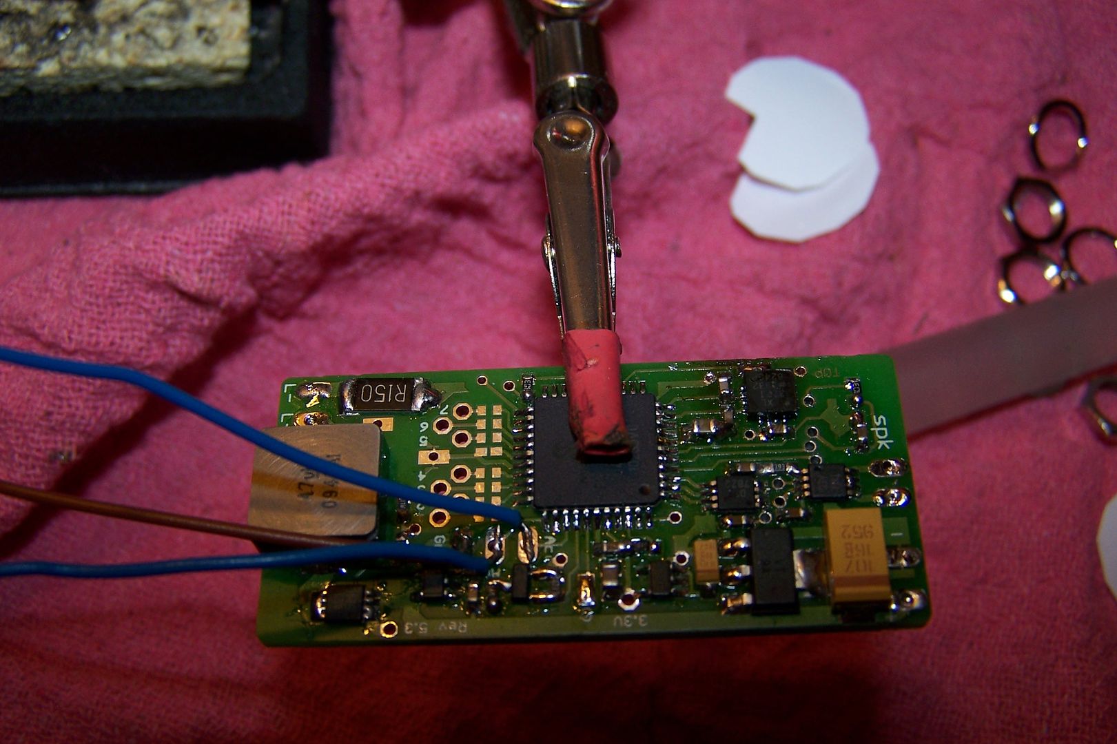
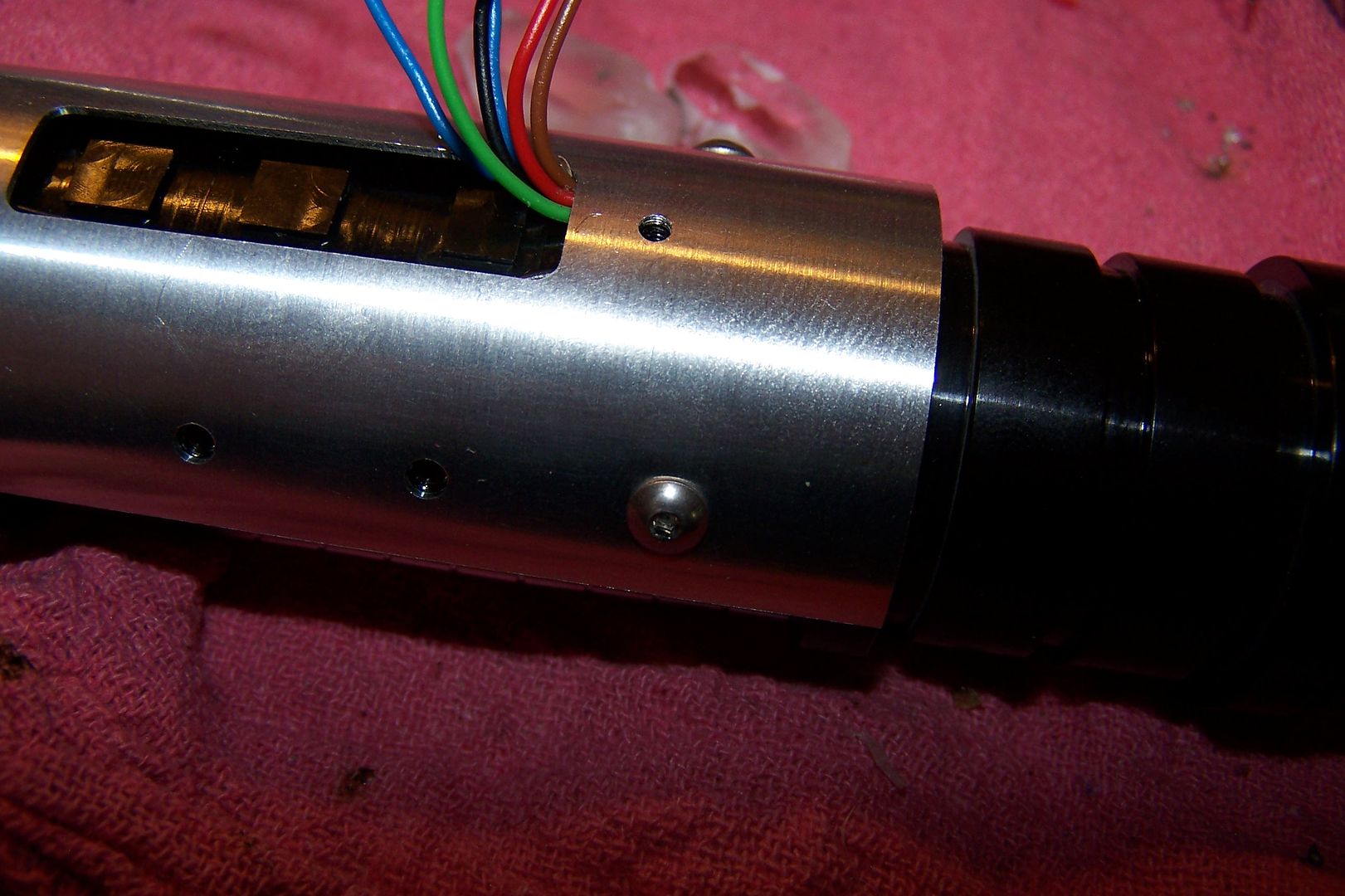
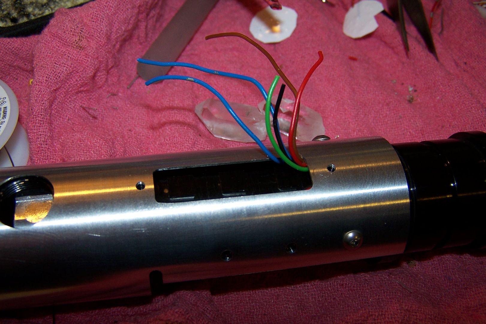
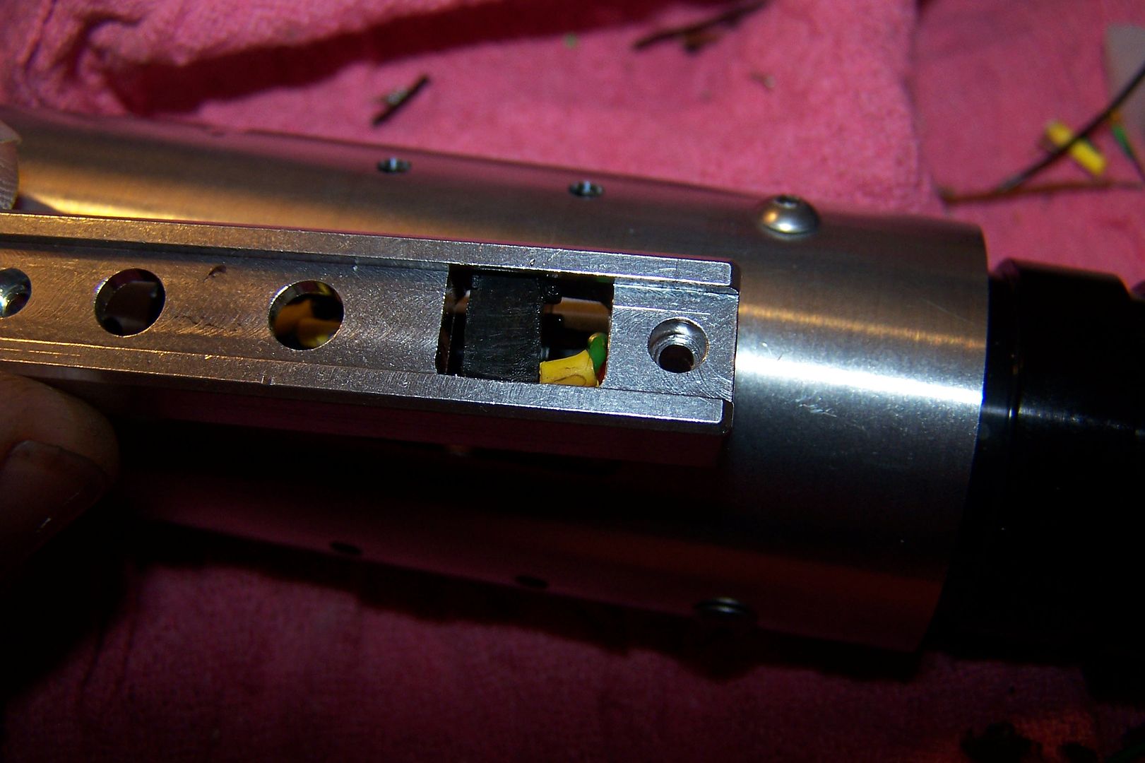
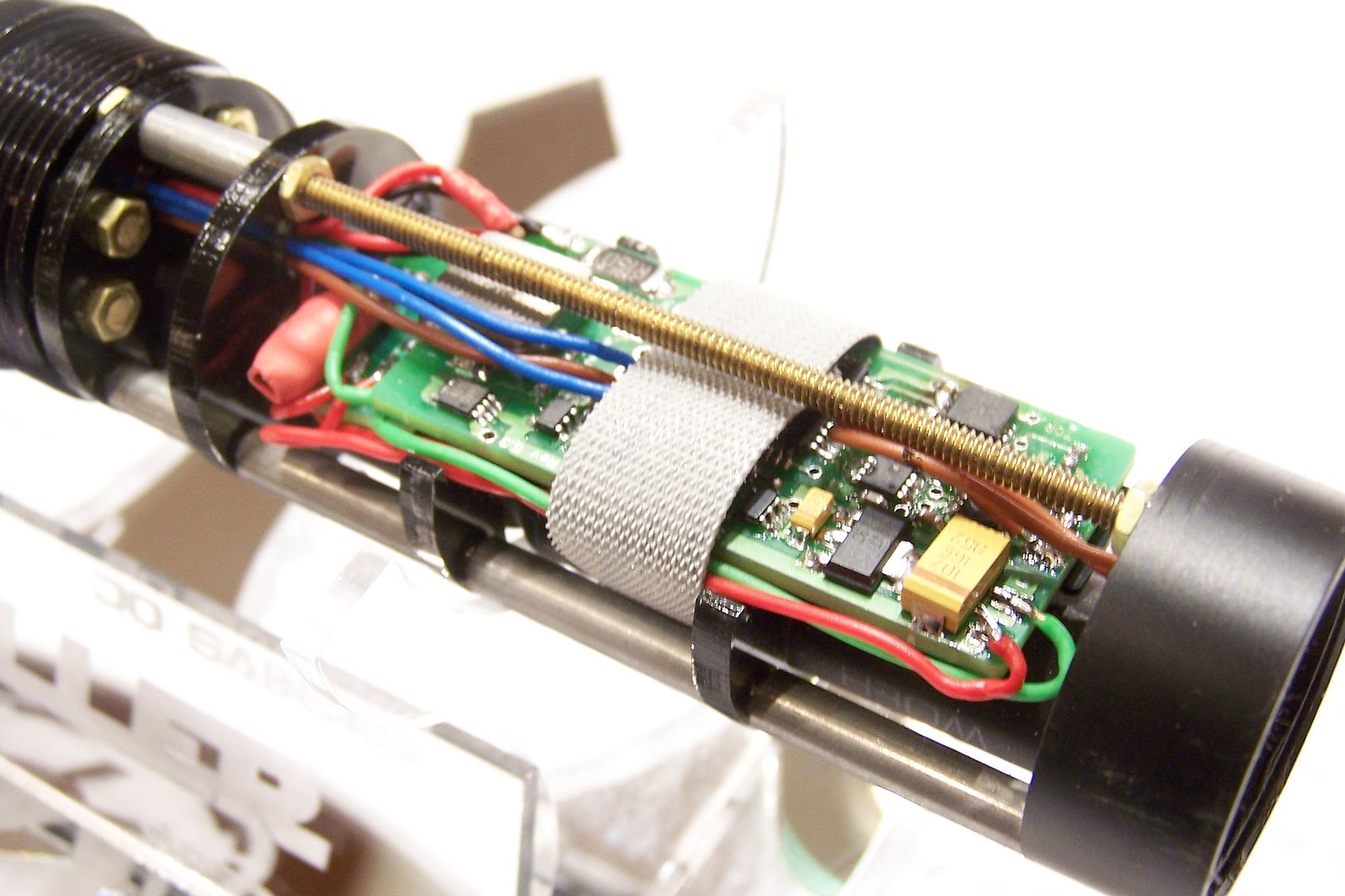
Once the CF is all wired, I pull all the wires through the wiring duct in the chassis and line them up in the order and orientation that I'll need once I pull them through the other side and after the shroud goes on.
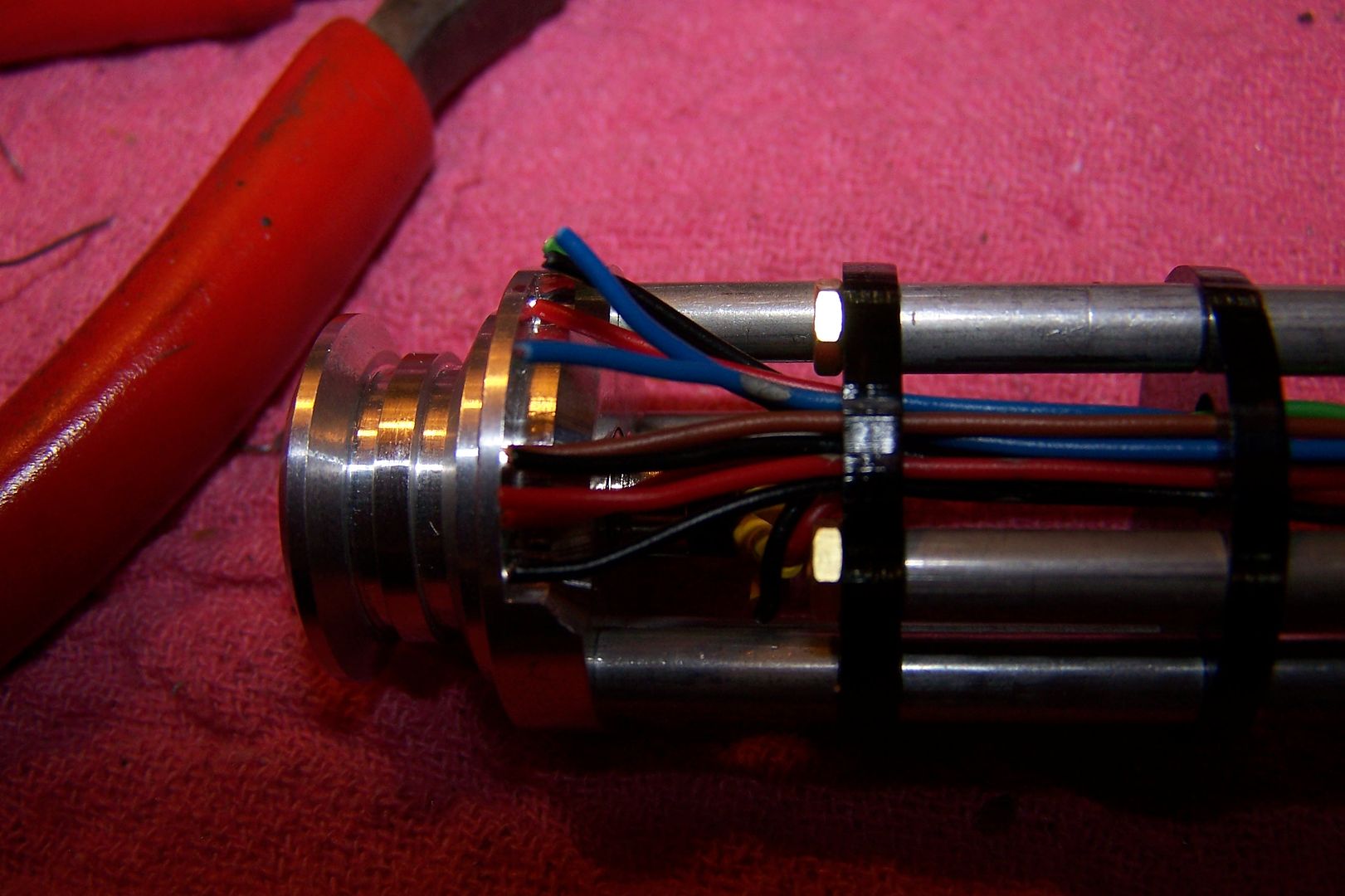
The chassis is then secured into the hilt and the wires are pulled through the port on the top of the body with some really fine tweezers.
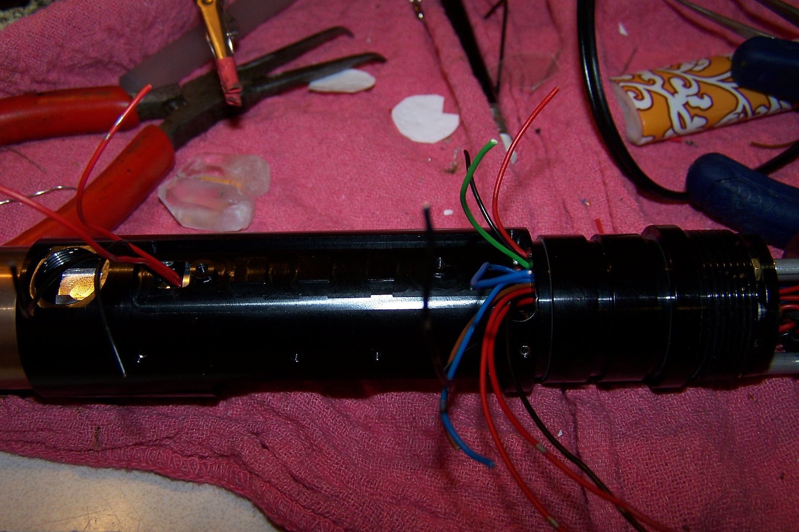
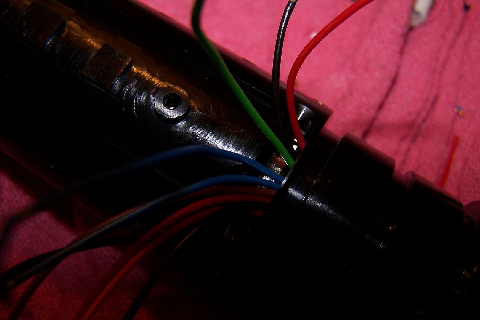
I then start by conecting the LED wires from the optics module to the LED wires from the soundboard. I have marked each wire with a code to tell me which lead goes to what. For some reason, no matter what I can't seem to have enough different colored wire.

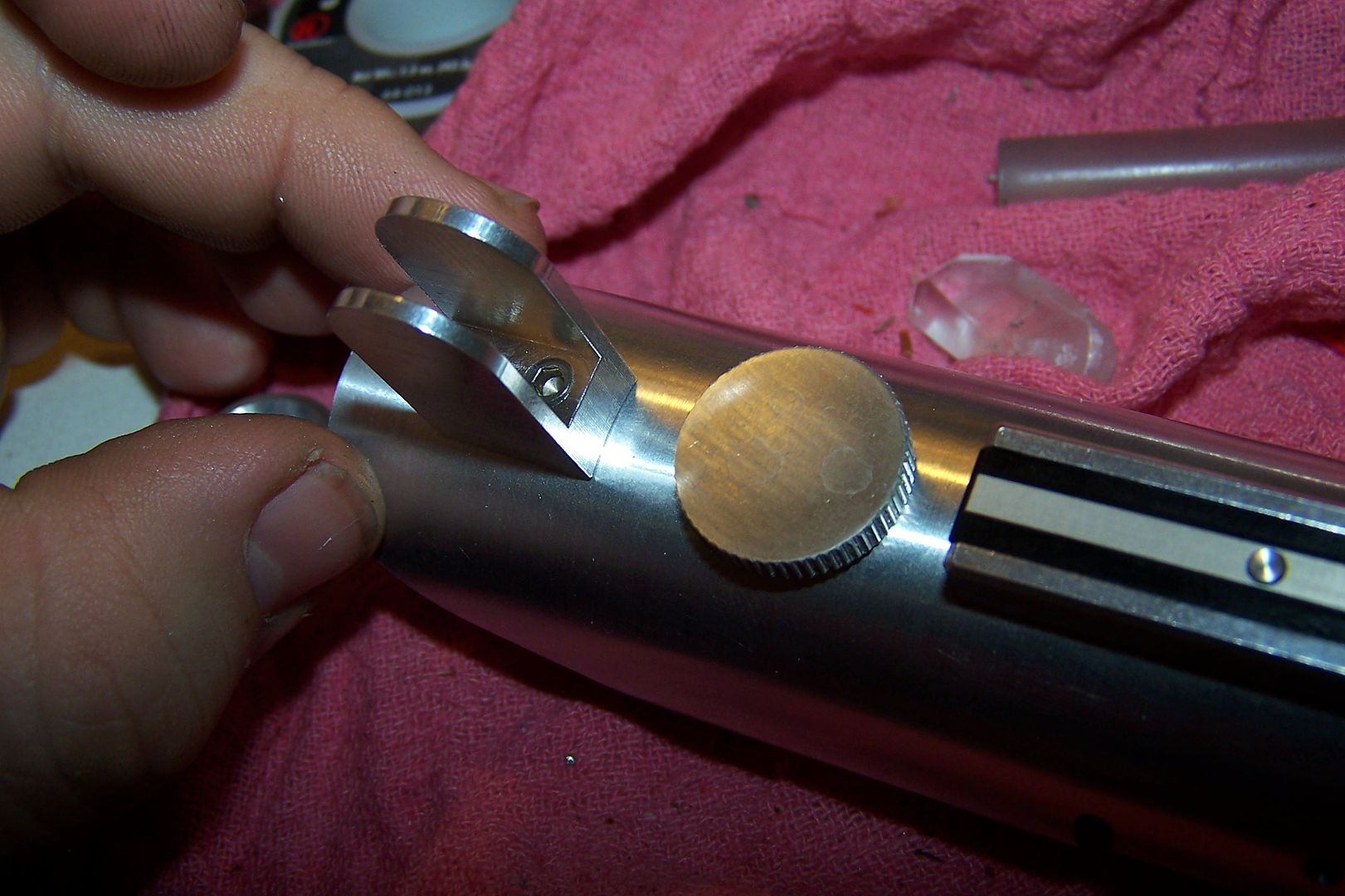
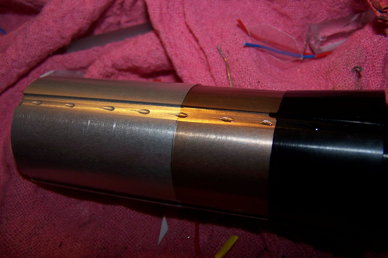
Once the LED leads are connected, I pull the slack out through the chassis, making the heatshrunk connections hide in the pocket through the wiring port. It is at this time that the aluminum support rods get put into place as they are partly held in by the shroud.
Then I tuck the rest of the wires flat and slide the shroud over and put one screw through it to hold it in place.
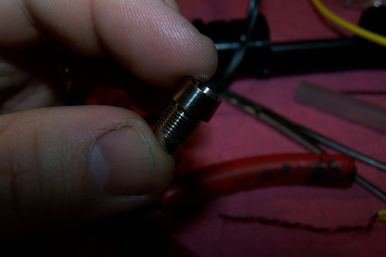
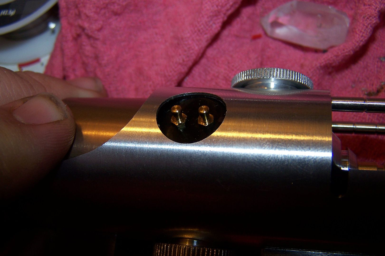
Then comes the most compact wiring I've ever done. I have to wire two tactile switches and a 1.3mm recharge port and squeeze it all into a space 1/4" wide by 1.5" long. I start by cutting off two of the switch contacts and filing them flush.

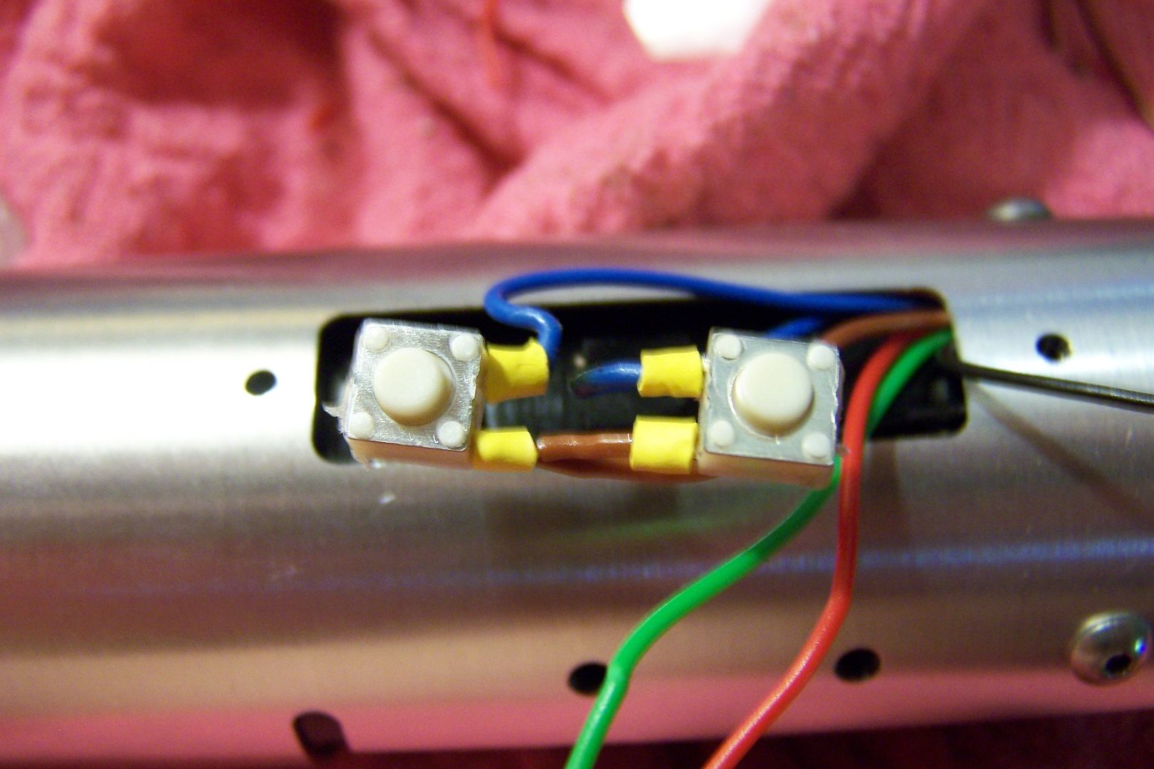
After soldering the switches and the recharge port, I glue the switches down on their posts that keep them at the proper height for the control box.
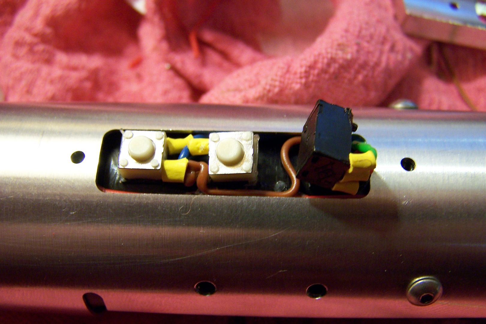
One thing that wasn't apparent during the design phase was that the pockets cut for the tactile switches in the control box, didn't allow for the wiring that has to go between them. It's hard to account for all this little stuff. So, out to the mill I went and used a 9/32 endmill to make a channel between the switch pockets to allow for the wiring.
I then push in the recharge port into it's pocket. This was such precision machining that it perfectly holds the port in place and then the post underneath it keeps it from moving at all.
I then screw down the box over the switches, then I place the aluminum switch hats over the switch plungers.
I also place the kill key in the charge port to cut power. I haven't yet soldered the positive lead to the board, but the key is there for when I do. It is at this time that I connect the last power lead and pop in a test SD card and test the electronics and look for bugs. Once everything is a go, I snap the speaker into the bucket and move on to the rest of the reassembly.
After the hats are in, I snap (yes, snap fit, it's so awesome) the card top in place on the box.
Now it's just a matter of screwing on some greeblies, the bunny ears and the brass replica Graflex pins.

Now it's time for the grip bars. Most of them were such a tight fit, that when hammered in with a rubber mallet they wouldn't have moved anyway, but I like to be careful so a light beading of Gorilla glue went under each one:
Erik made the replica Graflex Glass eye greeblie to accept a 10mm cabochon, some artistic forethought on his part. This was a little detail that I really loved, and we chose 10mm Paua shell cabs in blade color matching shades to go in each one.
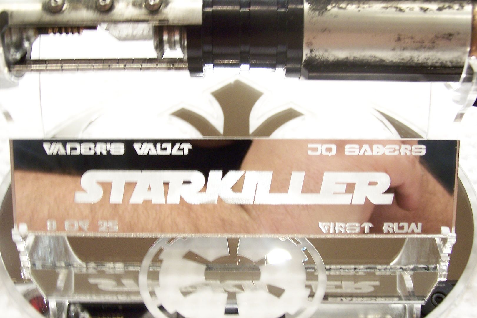
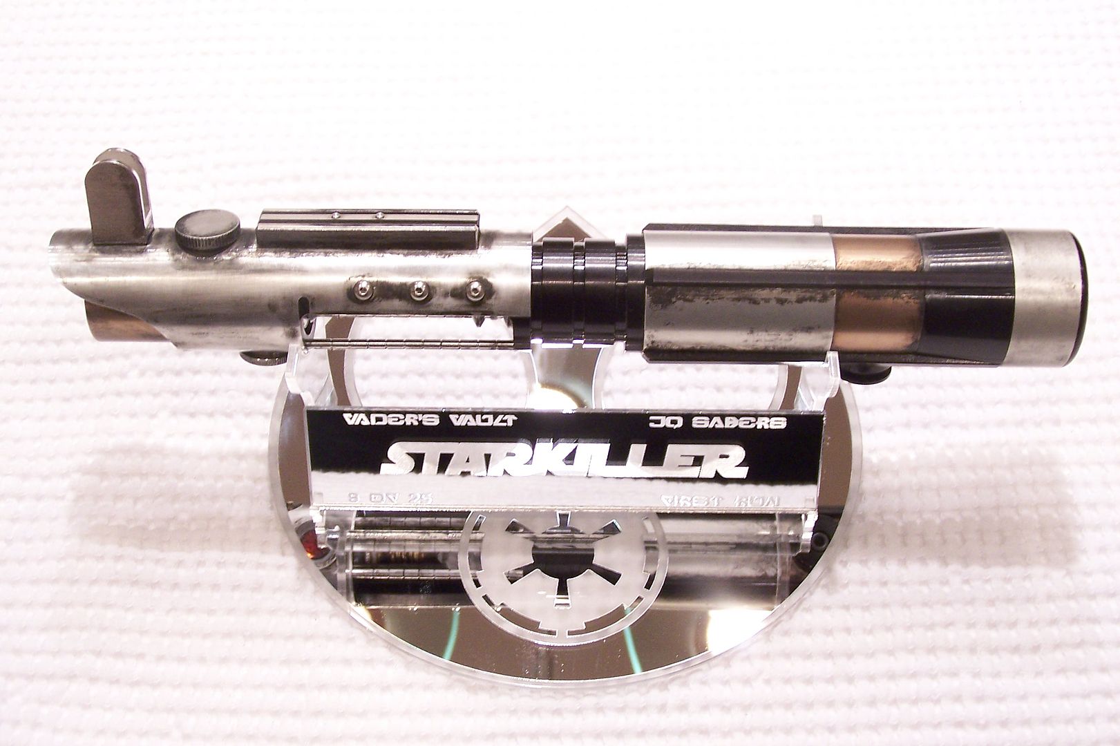
After that, some weathering done with Birchwood Casey aluminum black and some flat black paint we get this:
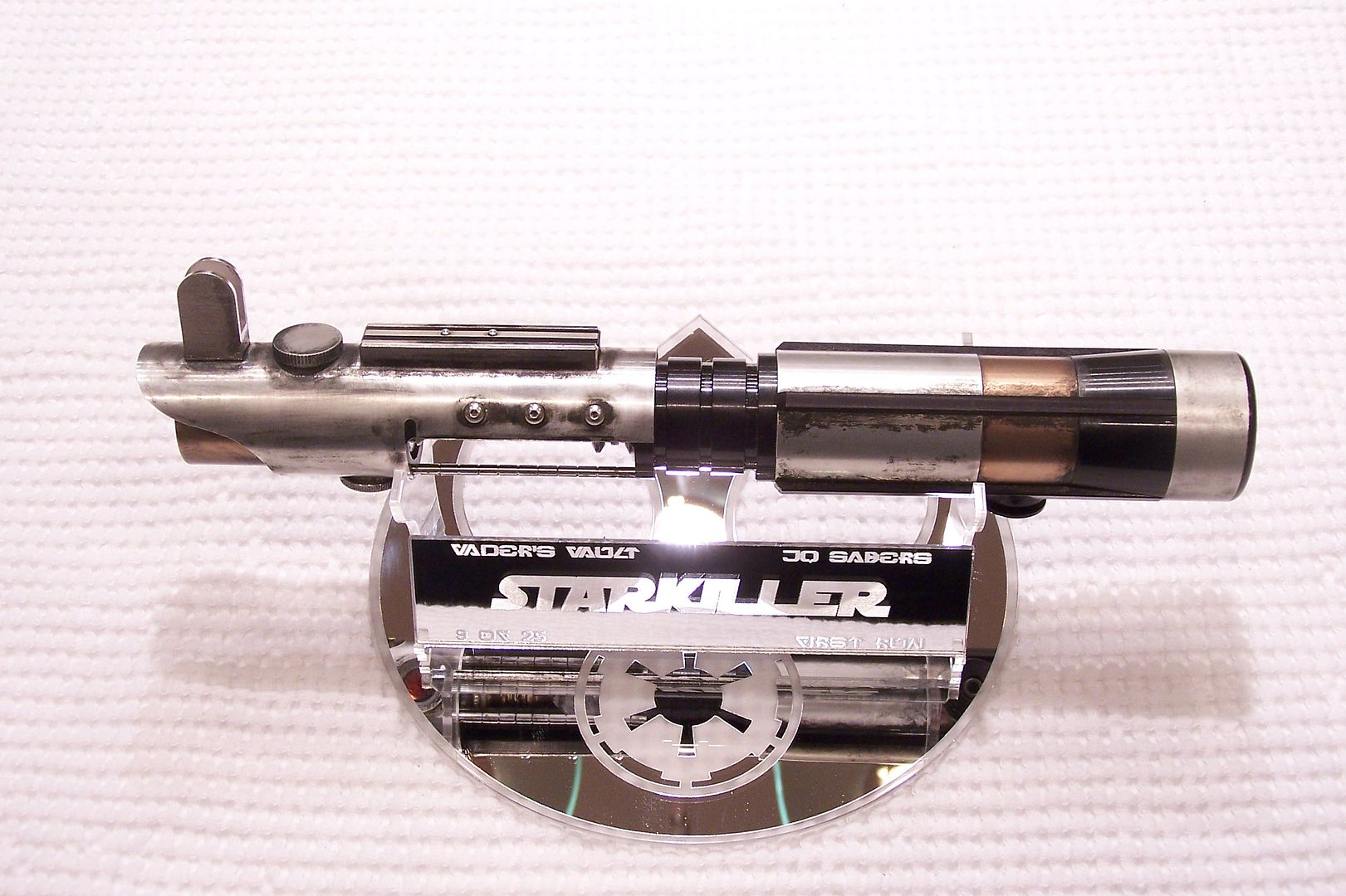
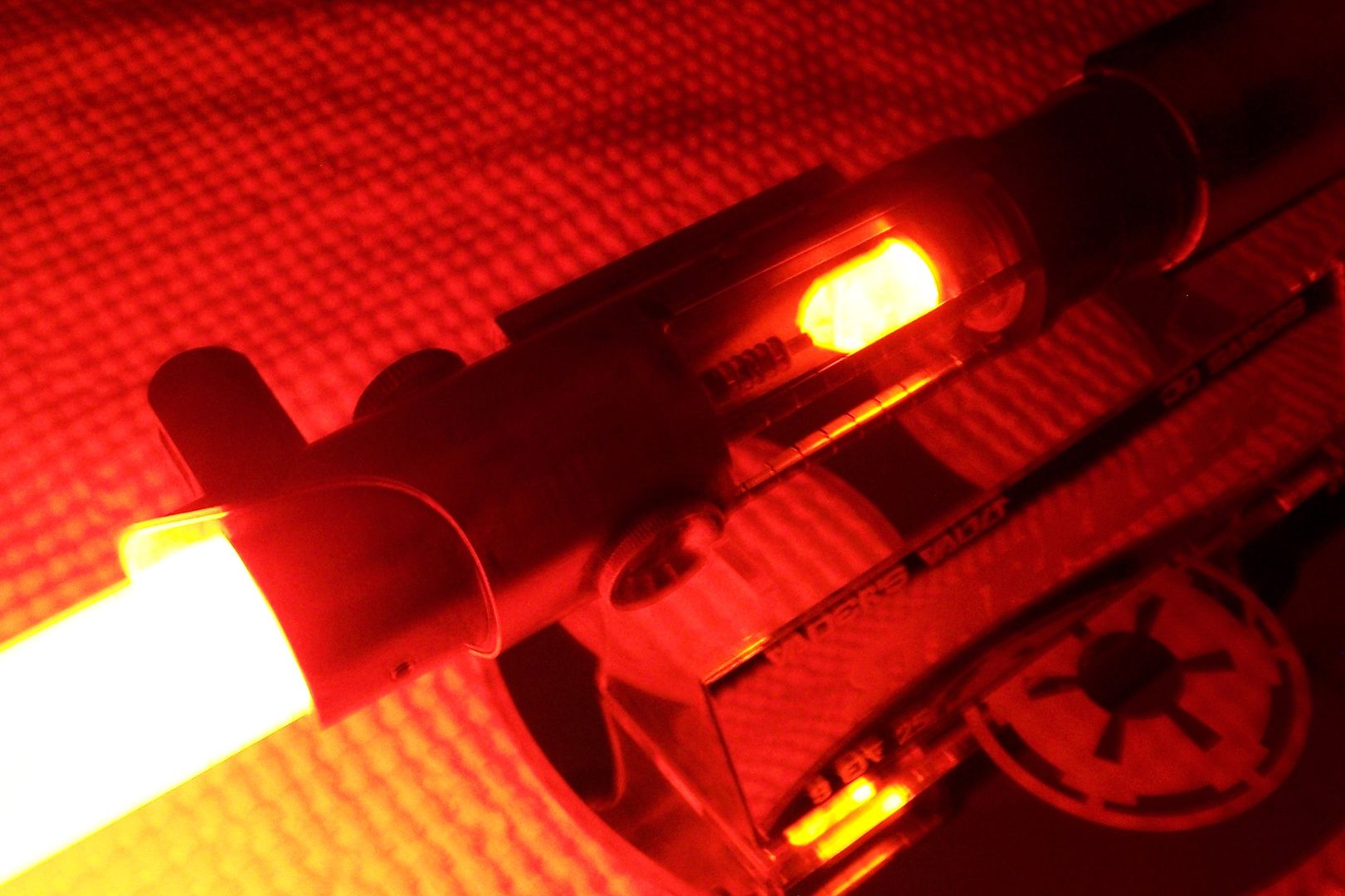

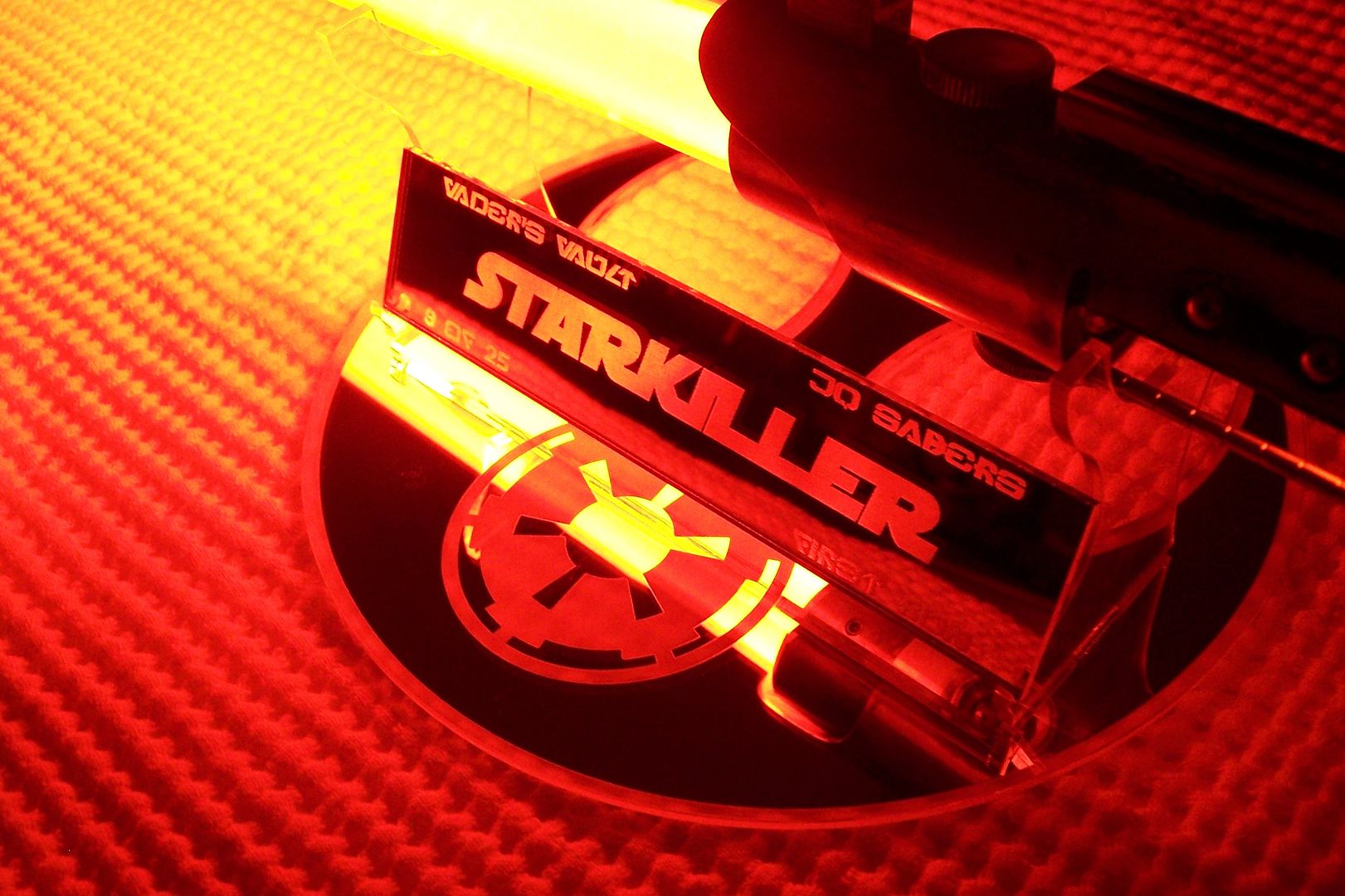
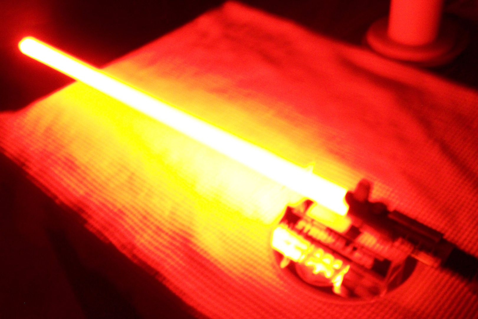
And the video:
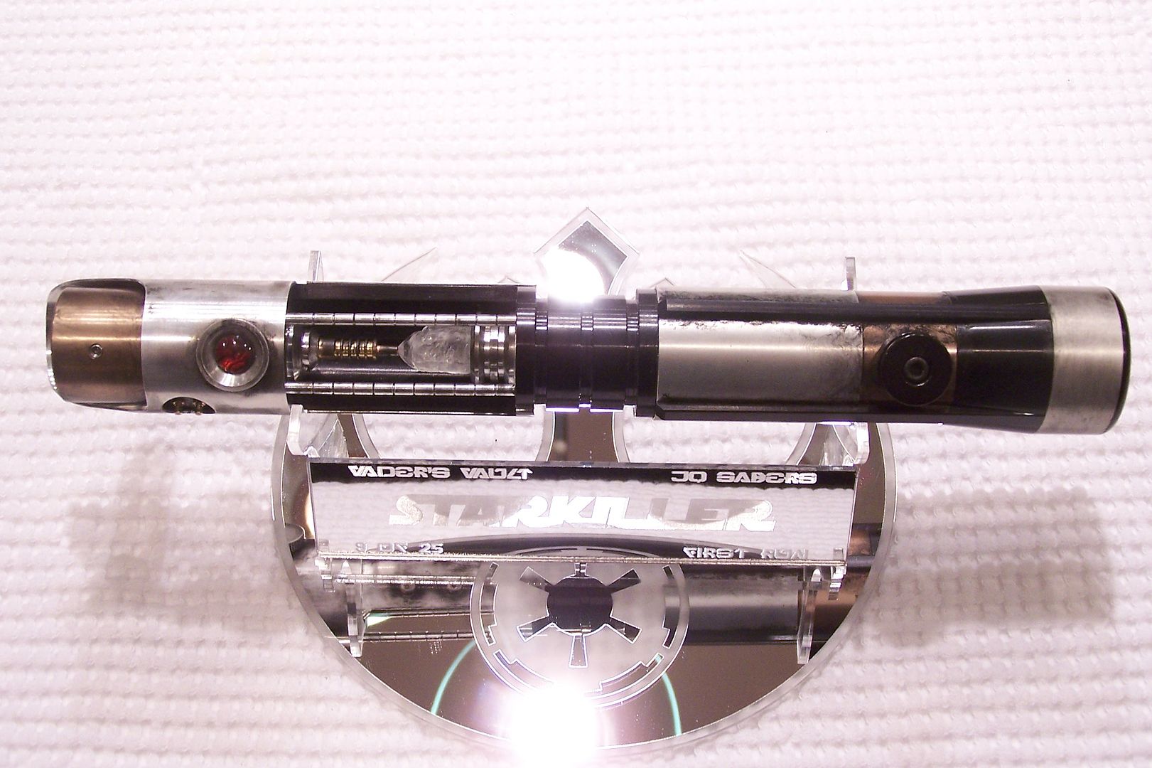
The Force Unleashed Starkiller Custom Lightsaber Crystal Focus V5 - YouTubeWell, I hope you enjoyed my quest and victory for the perfect Starkiller replica lightsaber. To all the people who were able to get one, thanks for sharing my dream!
 Topic: From Dream to Reality - The Vader's Vault Starkiller™ complete build log (Read 29148 times)